Track geometry monitoring from Graz, Austria

RIT Monitoring

Continuous monitoring of track geometry – at rest and under load. Sensors mounted directly on the rail foot report critical changes before they become a problem.

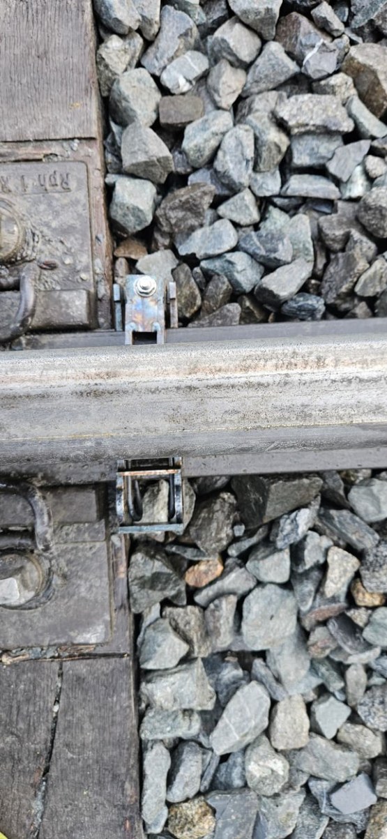
RIT sensor on the rail foot in the ballast bed
50sensors per gateway, typically about 100 m of track
15 mininterval at which readings are available in the RIT portal – shorter if required
0.5 mmaccuracy of deflection per axle, validated with a high-speed camera

01 · System overview

Two measuring tasks – one system

RIT Monitoring records track geometry at rest and under train load. Both states are evaluated separately – continuous monitoring instead of a snapshot.

Without load

Static track geometry

Continuous measurement of the track position at rest – parameters based on DB Ril 821.

Longitudinal levelVertical position along the track
AlignmentLateral position of the track
Cross levelHeight difference between the rails
TwistChange in cross level
Under load

Dynamic track geometry

High-frequency measurement at every train passage – based on the local deflection under each axle or wheel.

Deflectionper axle under train load
Axle detectionautomatic for every passage
Speedderived from axle detection
BogieDistance between bogies

From sensor to portal: one continuous data chain

01SensorsSensor fusion, on-board data processing and a fast interface in every sensor – plugged together in series to form the measuring chain.
02 · Sensor busGatewayConnects about 50 sensors and buffers data during transmission delays. Mounted on a railing or mast.
03 · Mobile networkServerReception, time stamping and limit checks. Rest and passage data are evaluated largely independently.
04RIT portalLive status, history, alarms and tickets for each monitoring project.

Measuring principle: from inclination to track geometry

Among other things, each sensor records its inclination across and along the track. The values of opposite and neighbouring measuring points add up to the track geometry.

Cross levelHeight difference between the left and right rail – determined from the cross inclination, relative to the track gauge of 1,435 mm.
Longitudinal levelThe longitudinal inclination of each segment and the spacing of the measuring points give the height profile along the measuring chain.
Unambiguous measuring chainSensors in opposite pairs on both rails, at defined (variable) intervals. Serial number and position of every sensor are stored in the project database.

02 · Installation & operation

Mounted like a rail foot clamp

Installed quickly, even during short possessions with traffic running. Track work is only needed to mount sensors and cables.

  1. 1
    MountThe sensor is fitted form-locked onto the rail foot with a hammer; the housing sits below the rail foot.
  2. 2
    SecureA locking piece on the opposite side is tightened with an impact wrench and ensures a correct fit.
  3. 3
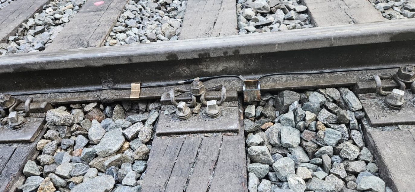
    ConnectThe permanently attached cables are plugged together, routed over the rail foot to the web and fixed with rail foot clips.
  4. 4
    CommissionAs soon as the measuring chain is connected to the gateway, the system can be commissioned. Removal is just as easy: take off the locking piece, unplug, release the sensor.
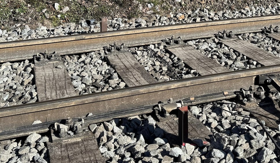
RIT sensor on the rail foot with cable routing
Mounted on the rail foot instead of the sleeper – closer to the rail head, so rail movement is captured more precisely.

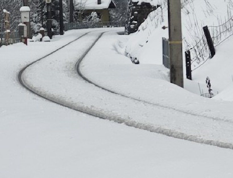
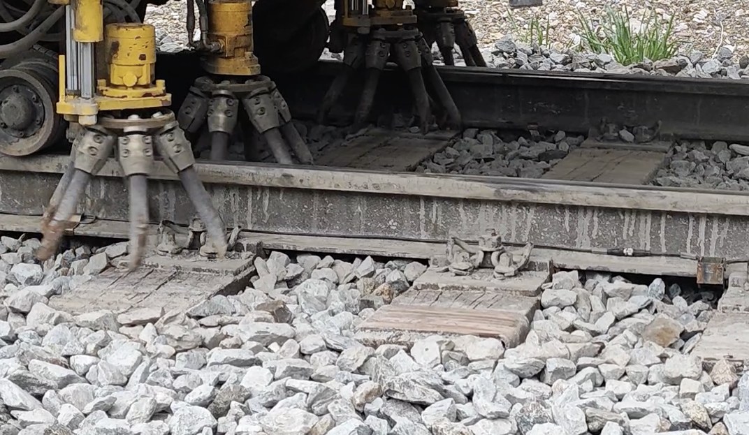
Proven in snow, snow ploughing and tamping

Snow-covered track in winter operation
Winter operationInstalled throughout the winter: full data even under snow cover. Several snow plough runs without damage.
Tamping machine during track maintenance
Tamping and maintenanceThe cable routing is approved for tamping. Apart from the branch cables, the system stays installed during tamping.
Sensors mounted protected below the rail foot
Protected designProtected against moisture and water; hard to reach below the rail foot. Cables are flame-retardant and highly UV-resistant.
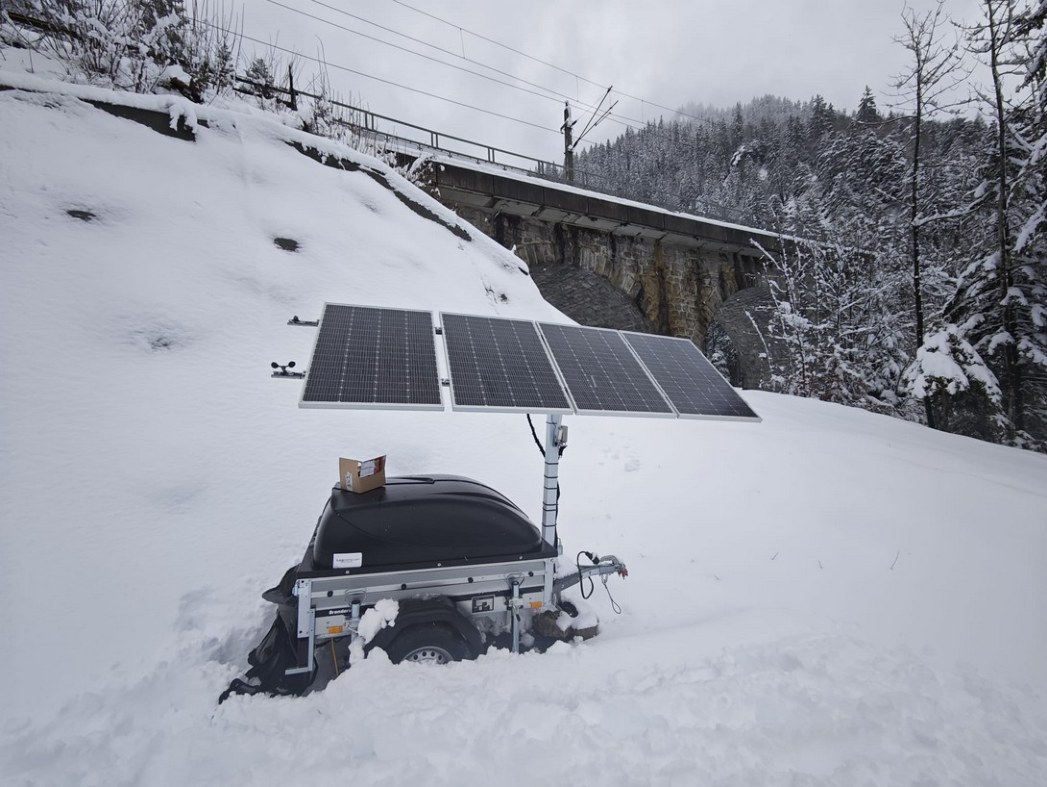
Photovoltaic trailer with buffer batteries in the snow
Self-sufficient supply via photovoltaics and buffer batteries in winter operation

Power supply: mains or self-sufficient

The gateway powers the connected measuring chains – from the mains or from photovoltaics, depending on the site.

Mains operationConnection to 230 V AC
Self-sufficient operationPhotovoltaics with buffer batteries, designed for several days without sun (e.g. in fog)
Automatic restartIf the batteries run empty, the system shuts down and restarts on its own as soon as enough energy is available again.
Integrated UPSBridges short interruptions when supply cables are plugged in or unplugged.

03 · Your benefits

Why RIT Monitoring

Static and dynamic measurement combined, without any optical methods – built for continuous operation, even in difficult conditions.

Early warningChanges are detected continuously.
Static and dynamicTrack position at rest and under load from one system, evaluated separately.
PreciseDeflection per axle with an accuracy of about 0.5 mm, validated with a high-speed camera.
RobustProven under snow cover, during snow plough runs and during tamping.
Quick to installMounted like a rail foot clamp – during short possessions with traffic running.
Flexible power230 V AC or self-sufficient via photovoltaics, with automatic restart.

Keep an eye on your line

Talk to us about your monitoring project – from designing the measuring chain to commissioning.